4. Basic viewing and manipulation
The default SPIERSview screen setup has the main view window (black) on the right, the ‘objects panel’ on the left, and progress panel at the bottom (see Fig. 1). The Main view window and the Zoom slider (see below) are permanently visible – the panels can be hidden, resized, repositioned or set to ‘float’ as the user desires. In addition to the two initially visible panels there are three more, the Clipping panel, Info panel and Pieces panel (discussed later). Panels are switched on and off using the view menu, or the keyboard shortcuts indicated in their title bars (F1, F2, F3, F4 and F6).
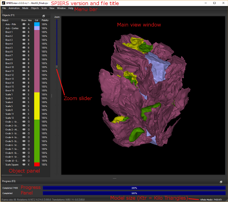
Figure 1. Default anatomy of a SPIERSview window
The status bar at the bottom gives total model size in KTr (1 Ktr = 1000 triangles). If objects are selected in the objects panel, the size given is for the selected objects only. A volume for selected objects is also given in cubic millimetres; this is calculated from raw data exported from SPIERSedit, and does not take into account any reduction from island removal, smoothing, fidelity reduction etc. Note that volume calculations are not currently corrected for any inconsistent slice-spacings specified in SPIERSedit.
When viewing models in SPIERSview finalised format (.spvf) or VAXML format (.vaxml), the interface is simplified; many menu options will not appear, and the pieces panel is not available. Volume measurements (see above) are also not available.
4.1. Moving, rotating and zooming
The model can be moved by dragging using the left mouse button, and rotated in three dimensions by dragging with the right mouse button. You can also rotate around the z-axis (the viewing direction) using the left and right arrow keys (hold shift down to make rotate faster), or by holding the shift-key down while dragging with the right mouse button. It is also possible to ‘lock’ the viewer into rotate mode by ticking the rotate lock command (Ctrl-R) on the Mode menu (this is primarily useful on single-button OSX systems). Also see “Touch screens” below.
The Simple Autospin command (Ctrl-U) on the Animation menu sets the model spinning around the y-axis (up/down on the screen) until the command is selected a second time. More advanced spins and animation exports are covered in the Animation System section (below).
The Zoom slider (see Fig. 1) is used to zoom the view; the Page Up and Page Down keys also perform the same function, as does the mouse-wheel (if present). Also see “Touch screens” below.
The Move closer and Move further commands ([ and ] keys) on the View menu are used to move the camera closer to or away from the model; this has a similar effect to zooming, but may be preferable if, for instance, the model is so close to the camera that perspective distortions are unacceptable. Hold shift down ({ and } keys) for larger moves closer or away. Note that in Orthographic mode there will be no visible effect of moving the model backwards or forwards in this way.
4.2. Touch screen support
Modern computers with touch screens should be compatible with SPIERSview for basic object moving, roatating, and zooming. The model can be moved by one finger dragging, and rotated around around the z-axis (the viewing direction) using two finger rotation. Rotated in three dimensions can be achieved by toggling the rotate lock command (Ctrl-R), or by holding down Crlt while one finger dragging. Zooming in/out can be achieved by using the two finger pinch-to-zoom gesture.
4.3. Object visibility
SPIERSview models consist of a number of objects and groups of objects (see below) which are listed in the Object panel on the left of the screen (Fig. 1). Each object is normally given a different colour, and each object or group can be independently turned on or off (hidden from view), enabling the user to perform ‘virtual dissections’. This can be done by double-clicking the ‘eye’ icon for each object in the object panel (see Figure 1), or by using the keyboard key assigned to the object (the single character A-Z or 0-9 visible to the right of the eye icon). Objects are not required to have a key assigned, in which case they can only have their visibility toggled with the ‘eye’ icon. If a group is hidden then all objects or groups within it, irrespective of their visibility setting, are not visible.
The objects menu has Show All (Shift+H) and Hide All (Ctrl+H) commands which can be used to set the visibility of all objects either on or off. An Invert Show (Crtl+I) command also exists, which hides all currently shown objects, and vice versa.
Note that transparency (see section on transparency later on) can be used as an alternative to simply hiding objects in some situations.
4.4. Stereoscopic 3D viewing
SPIERSview can run in several 3D display modes (top five options in the Mode menu). These are:
Orthographic (Ctrl-O): Orthographic rendering without perspective effects (distant objects will not appear any smaller than close ones). This is mode is useful for measuring specimens, in conjunction with the scale grid.
Perspective (Ctrl-P): Normal display without any form of stereoscopic 3D, but with perspective rendering (distant objects will appear smaller). This is the default.
Anaglyph Stereo (Ctrl-A): Anaglyph stereo mode splits the left and right eye images using red (left) and cyan (right) filters, and allows 3D viewing using red/cyan or red/green glasses; the former will work better, but the latter are normally adequate. This is intended as a cheap and effective means of viewing 3D images, but (unlike Split Stereo or QuadBuffer Stereo modes) does not fully preserve colour information. Anaglyph stereo viewing may also be hampered if the model contains strong colours; the Mute Colours command (Ctrl-M) on the Mode menu can help in these cases, as it reduces colour saturation.
Split Stereo (Ctrl-S): This mode splits the Main view window in two, displaying the left and right eye images in the left and right halves. Direct viewing in this mode requires viewer to be able to separately focus on each image. Screen captures (see below) in this mode can be used to generate printed stereo-pairs for viewing with a magnifying stereoscope.
QuadBuffer Stereo (Ctrl-Q): This mode sends the left and right eye images separately to the OpenGL rendering system where they can be interpreted by dedicated 3D display hardware. Most 3D display systems can handle OpenGl QuadBuffer input, and hence SPIERSview should be able to use this mode to produce stereoscopic 3D output using most 3D screens and projectors. Please note that no guarantee of success for any particular hardware can be provided.
The user may find that the default ‘medium’ stereo-separation (the strength of the stereoscopic effect) is too high or too low in some situations. Stereo-separation can be set to one of five preset strengths, accessed through the View menu or using the keyboard shortcuts Alt+1 (very low) through Alt+5 (very high).
4.5. Full Screen Mode
SPIERSview can run in a full screen (Crtl+F) mode where the 3D view is maximised to the maxiumum monitor height and width. Under Windows a frameless and undecorated window is produced. While under Linux a minimal framed and decorated window is used. When in full screen mode use (Crtl+F) to toggle back to normal mode.
Note that under full screen mode only the 3D view is displayed, all other pannels and menus are not shown. However, all shortcut key combinations will still work.
4.6. Background Colour
By default SPIERSview uses a black background for specimens, but this can be changed at will using the Background Colour… command on the View menu. Changes to the background colour are saved in SPV files, but not in VAXML or SPVF files.
4.7. Bounding Box Mode
Selecting the Bounding Box Mode command on the Mode menu causes all items to render as wireframe boxes. Bounding box rendering is far faster than normal rendering, and may, for instance, assist with the initial placement of objects when assembling multi-piece models.